
Precision Aluminum CNC Hole and Thread Design Guide
Designing for CNC machining requires balancing functional requirements with manufacturing efficiency. When working with aluminum, specific geometric constraints—particularly concerning holes and threads—directly impact tool life, cycle times, and dimensional stability.
At CNCALPARTS, we specialize exclusively in aluminum CNC machining. Our experience with 6061, 7075, and other alloys allows us to provide actionable DFM insights that streamline production from prototype to batch manufacturing.
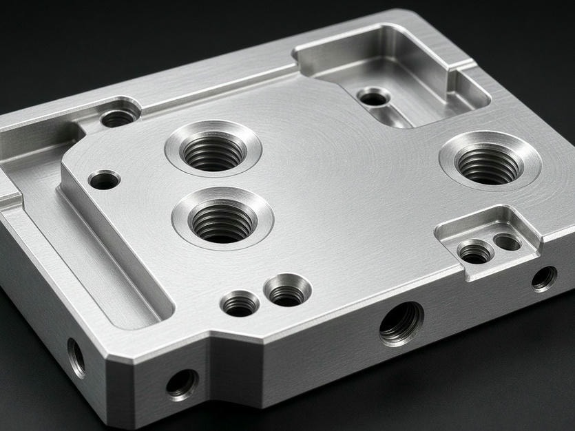
Standard Hole Features: Best Practices
To ensure high-precision results, your CAD models should account for the limitations of end mills and drill bits.
Hole Depth
For optimal tool rigidity, keep hole depths within 3x the diameter. Deep holes (exceeding 5x–8x diameter) increase the risk of tool deflection, which can lead to tapered holes or broken tooling.
Edge Distance
Ensure holes are positioned at least 1.5x the hole diameter away from the part edge. Placing holes too close to an edge can cause the thin aluminum wall to deform or tear during drilling.
Hole Transitions
Avoid holes that intersect with angled surfaces. If a drill enters an angled surface, the bit tends to "walk," resulting in poor positional accuracy. If you must intersect an angled surface, add a flat spot or a counterbore to provide the tool with a perpendicular entry point.
Threading and Tapping Guidelines
Aluminum is a soft, ductile material, which makes it excellent for machining but susceptible to thread stripping if not designed correctly. These three rules keep tapped holes reliable and repeatable.
Rule of thumb
Thread engagement of 1.5x diameter is the standard. Beyond 2x diameter, pull-out strength gains diminish while tap breakage risk rises.
- Thread Length
- The standard rule of thumb is a thread engagement length of 1.5x the diameter. Extending threads beyond 2x the diameter provides diminishing returns in pull-out strength and increases the risk of tap breakage in the hole.
- Threaded Holes vs. Helicoils
- For high-load applications or parts requiring frequent assembly/disassembly, consider using thread inserts (Helicoils). If you plan to use inserts, specify the appropriate drill size for the insert tap in your documentation.
- Chamfers
- Always include a chamfer at the entrance of a threaded hole. This prevents "burr buildup" at the top of the thread, which is critical for smooth fastener installation and cosmetic finish requirements.
Precision Features: Reaming and Boring
When a standard drilled hole does not meet your tolerance requirements (typically ±0.05 mm), we utilize reaming or boring to achieve higher precision.
Tolerance Control
For fits requiring ±0.01 mm, specify reamed holes on your engineering drawings.
Surface Finish
Reaming produces a significantly smoother internal surface (Ra 0.8 μm) compared to standard drilling, which is essential for hydraulic manifolds or optical mounting components.
Design for Accessibility
Ensure your design allows for the necessary tool clearance for the reamer or boring bar. If the hole is at the bottom of a deep, narrow cavity, it may be physically impossible to reach with the required finishing tool.
Counterbores and Countersinks
Properly designed counterbores facilitate clean, flush-mounted hardware, which is standard for high-end aluminum enclosures and structural brackets.
Standard hardware and consistent sizes let us optimize tool changes and reduce total cycle time.
| Design Factor | Recommendation | Impact |
|---|---|---|
| Standardization | Use standard fastener sizes for your counterbores. | Non-standard dimensions often require custom tooling, adding unnecessary lead time and cost to your project. |
| Uniformity | Minimize the number of different hole and thread sizes on a single component. | Using a consistent set of hardware across your assembly allows us to optimize tool changes and reduce total cycle time. |
DFM Checklist for Your Next Project
Before finalizing your 3D models and technical drawings, review your design against these critical factors.
1. Tolerance Reality
Are your ±0.01 mm tolerances functionally necessary? Tight tolerances on every feature increase inspection time and production costs. Apply high-precision callouts only where required.
2. Tool Access
Can a standard tool reach the feature? Complex 5-axis components often require long-reach tooling, which can lead to vibration and reduced surface quality.
3. Wall Thickness
Ensure that drilling or tapping operations do not leave walls thinner than 0.5 mm, as this will lead to deformation during the machining process.
4. Drawing Clarity
Always provide a clear PDF engineering drawing alongside your STEP files. Clearly mark critical dimensions, hole diameters, and thread specifications.
Why CNCALPARTS for Aluminum?
General machine shops often treat aluminum as a secondary material. We treat it as our specialty. By focusing exclusively on aluminum, our team has mastered the unique challenges of chip evacuation, thermal expansion control, and surface finishing for anodized parts.
Whether you are working on robotic housings, heat sinks, or precision optical mounts, our DFM expertise ensures that your parts are manufactured efficiently without sacrificing quality.
- Aluminum Only
- DFM Expertise
- Prototype to Batch
CNCALPARTS
Aluminum CNC Machining Specialists
We Machine Aluminum. Only Aluminum.
Get Your Project Started
We support projects from one-off prototypes to recurring batch production. If you have a design ready for review, send us your 3D models and PDF drawings to get a quote and professional DFM feedback.
- info@cncalparts.com
- Phone
- Address
Request a Quote & DFM Review
Share your STEP files and PDF drawings. We respond with pricing and manufacturability feedback.